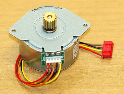
H-bridge is frequently used to control DC motors and stepper motors. When controlling a bipolar stepper motor, two full H-bridges are needed. There are many H-bridge ICs (like L298, MPC17529 and SN754410 which is a quad half H-bridge) for just that purpose. But if you are on a budget, you may want to consider building a dual H-bridge yourself. The following schematic shows a simple dual H-bridge using eight general purpose transistors (2N3904 and 2N3906). Given the maximum current of roughly 200mA, this circuit can be used to drive a small bipolar stepper motor operating between 5V and 12V, such as the stepper motors found in most floppy drives and CD / DVD drives.
Posted on Thursday, May 5, 2011 • Category:
Stepper Motors
Stepper motors are everywhere in electronics these days. There are two main types of stepper motors:
1. Bipolar motors. These have two coils and are controlled by changing the direction of the current flow through the coils in the proper sequence. These motors have only four wires and cannot be connected to this kit. See our Kit 1406 for a Bipolar Stepper driver Kit.
2. Unipolar motors. These have two center-tapped coils which are treated as four coils. These motors can have five, six or eight wires. Five-wire motors have the two center-taps commoned internally and brought out as one wire (Fig 1). Six-wire motors bring out each center-tap separately. The two center-taps need to be commoned externally (Fig 2). Eight-wire motors bring out both ends of each coil. The four “center-taps” are joined externally to form one wire. In each case the center-tap(s) are connected to a positive motor power supply. Unipolar motors may be connect as bipolar ones by not using the ‘+’ wires.
A stepper motor has no brushes or contacts. It is basically a synchronous motor with the magnetic field electronically switched to rotate the armature magnet around.
The Internet is where to get all the explanation about steppers. Just google ‘stepper motor’ and you will find tens of sites. In particular, look for ‘Jones on Stepper motors’ (it comes up top of the list when I did it just now) and read it. If you look at the other references you will find that the circuit in this kit has been around for many years in various forms. The latest publication was in Silicon Chip, 5/2002, and I have based this circuit on it.
Posted on Tuesday, April 8, 2008 • Category:
Stepper Motors
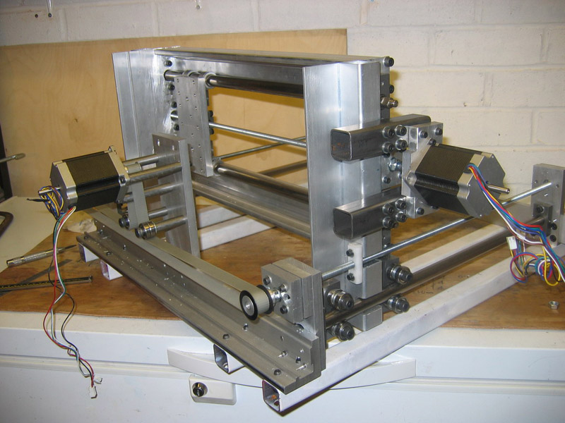
This is an easy to build stepper motor driver that will allow you to precisely control a unipolar stepper motor through your computer's parallel port. With a stepper motor you can build a lot of interesting gadgets such as robots, elevator, PCB drilling mill, camera panning system, automatic fish feeder, etc. If you have never worked with stepper motors before you will surely have a lot of fun with this project.
Circuit-Zone.com © 2007-2025. All Rights Reserved.