Circuit-Zone.com - Electronic Projects
Posted on Saturday, March 30, 2013 • Category: FM Transmitters
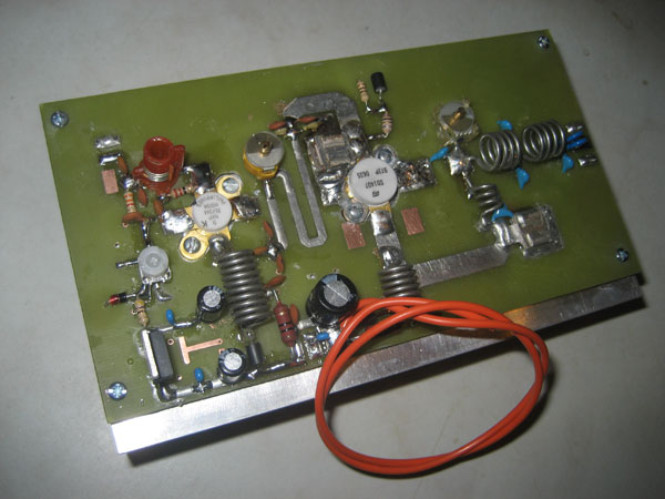
This is 150W FM transmitter amplifier for 88-108MHz band. The amplifier has two stages using BLF244 mosfet transistor for the first stage which requires 0.5 - 1Watt of RF input to get about 20watts to drive the final stage SD1407 which can push nearly 200 Watts on this design.
This design is more or less broadband however I added two variable capacitors after each stage for optimum matching and power output. Make sure the trimmer and the capacitors after the final stage SD1407 are a high voltage types with at least 200V rating. The power on this amplifier can be varied by adjusting the bias voltage using the white pot to the BLF244 mosfet. I added a zener diode onto the bias supply to protect the transistor from too much bias voltage.
Posted on Sunday, March 24, 2013 • Category: Power Supplies
 Here's how to build your own adjustable power supply based on LM317. The IC LM317 is so versatile that an almost unlimited number of different, small, high grade power supply circuits can be built using it. The configurations can be introduced for different applications for upgrading an existing unit with features that would virtually make it indestructible.
A few useful application circuits using IC LM317, collected from National Semiconductor's PDF datasheet are meticulously explained in this section with the help of the relevant circuit diagrams. All the circuits discussed below require an unregulated input voltage (max. 35 Volts) from any standard transformer/bridge/capacitor network.
Posted on Wednesday, March 20, 2013 • Category: FM Transmitters
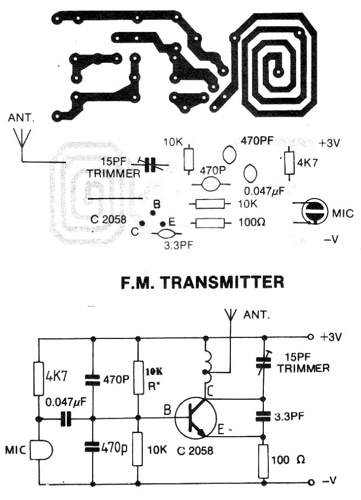
 This tutorial is for making simplest FM transmitter using only one transistor. VC1 is a small, screw-adjustable, trimmer capacitor and its rating should be around 10-100pF. Set your FM receiver for a clear, blank station. Then, with a non-conductive tool, adjust the capacitor for the clearest reception, rotate it till the receiver receives a sound from the microphone of transmitter. Use the following formula for determining the frequency.
Posted on Friday, March 15, 2013 • Category: AM Radio
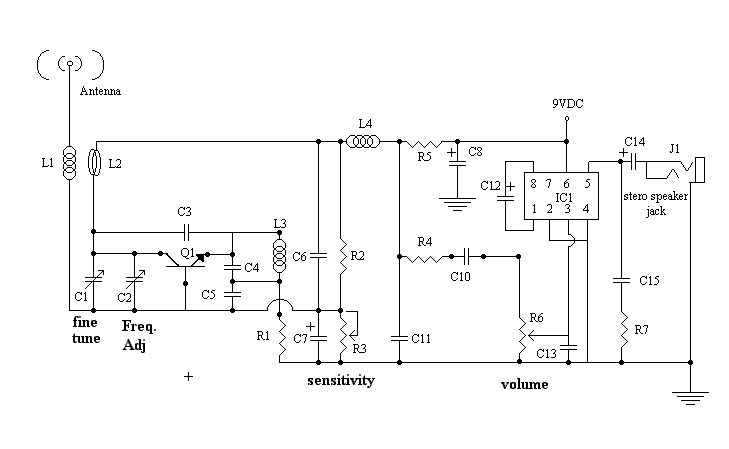 VHF FM Aircraft Receiver is a superregenative receiver developed for listening to FM transmitters but also tunes the aircraft band and the top portion of the FM broadcast band. Receives both AM and FM (107mHz to 135 MHz). You can use this receiver with the any FM transmitter. The receiver is amazingly simple using only one transistor for the receiver section and one IC for the audio section. This circuit is a self-quenching regenerative RF receiver also known as a superregenerative receiver. A superregenerative receiver performs two basic functions. First it feeds back a portion of the received signal from it’s output in phase to its input; and second a super audible quenching oscillator drives the amplifier through the point of oscillation and maximum sensitivity and then quenches the oscillation repeatedly. This keeps the feedback from driving the circuit into self-oscillation and allows the signal to be regenerated over and over again. In this version of the circuit, both functions are performed by the circuitry associated with Q1.
The rest of the circuit, shown to the right of L3 in the schematic, comprise the audio amplification circuit and are centered on the LM386 Audio Amp IC. In this configuration the LM386 is set at a gain of 200 and feeds it’s output to a standard 1/8-inch diameter stereo phone jack. The audio can then be heard by plugging any standard stereo headset into the jack.
Posted on Monday, February 25, 2013 • Category: FM Transmitters
 For months I’ve been looking for a simple FM BUG project, the ones online require inductors which you either have to acquire or build, if you don’t have a LCR meter it becomes rather hard to get the circuit working, specially if you’re a beginner without an oscilloscope! – Sometimes they don’t even tell you which inductance is required and you have to calculate an estimate, which is the main reason why many high frequency RF projects fail in the first place. This circuit on the other hand performs pretty well, even if you’re manipulating the board or touching the coax it will stay within the tuned frequency (unless you touch the transistor or timing capacitor!).
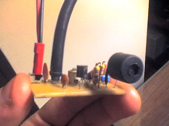
Posted on Saturday, February 16, 2013 • Category: FM Transmitters
 The objective of this 3V FM Transmitter design is to provide a simple low-power transmitter solution for broadcasting audio from various audio sources. This transmitter transmits audio using small sensitive microphone. Transmitter's frequency, as built is tunable via 15pF trimmer to the desired frequency, and the coil is embedded on the circuit board. This implementation is adapted to rebroadcast the output of a CD player, television receiver, or radio receiver. I use this transmitter so that I can move about the house and listen to my favorite programs without disturbing others. Within and the house, I find that I can get 50 to 100 meters away from the transmitter with the small pocket FM receiver I carry in my shirt pocket.
Posted on Sunday, February 10, 2013 • Category: FM Transmitters
 This little broadcast FM transmitter has 500mW of RF output power and runs of 12-15V battery or power supply. DC whose signal modulated by FM using four transistors. Transmitter includes four transmitter stages and draws around 100-150mA of current. Using the values of the circuit components, the frequency will be around 100 MHz but can be changed via coil. Through the 5 pF capacitor and 10K ohm resistor, the modulation of audio signal is supplied to the tank circuit. The amount of modulation is being managed by the 1N4002, a general purpose rectifier diode. FM Transmitter's output stage is functioning as a class D amplifier where the output transistors act as a switch.
Posted on Tuesday, January 29, 2013 • Category: Test and Measurement
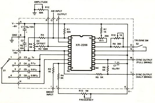 This is high quality function generator system using the XR2206 chip. Waveform function generator capable of producing AM/FM modulated sine wave outputs find a wide range of applications in electrical measurement and laboratory instrumentation. This application note describes the design, construction and the performance of such a complete function generator system suitable for laboratory usage or hobbyist applications. The entire function generator is comprised of a single XR2206 monolithic IC and a limited number of passive circuit components. It provides the engineer, student, or hobbyist with highly versatile laboratory instrument for waveform generation at a very small fraction of the cost of conventional function generators available today.
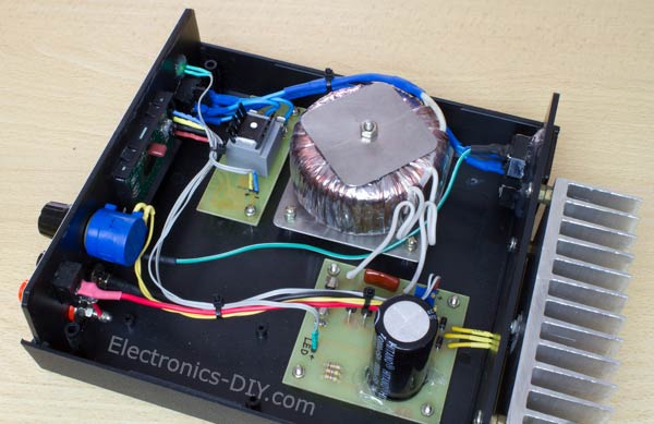
Posted on Thursday, January 24, 2013 • Category: Power Supplies
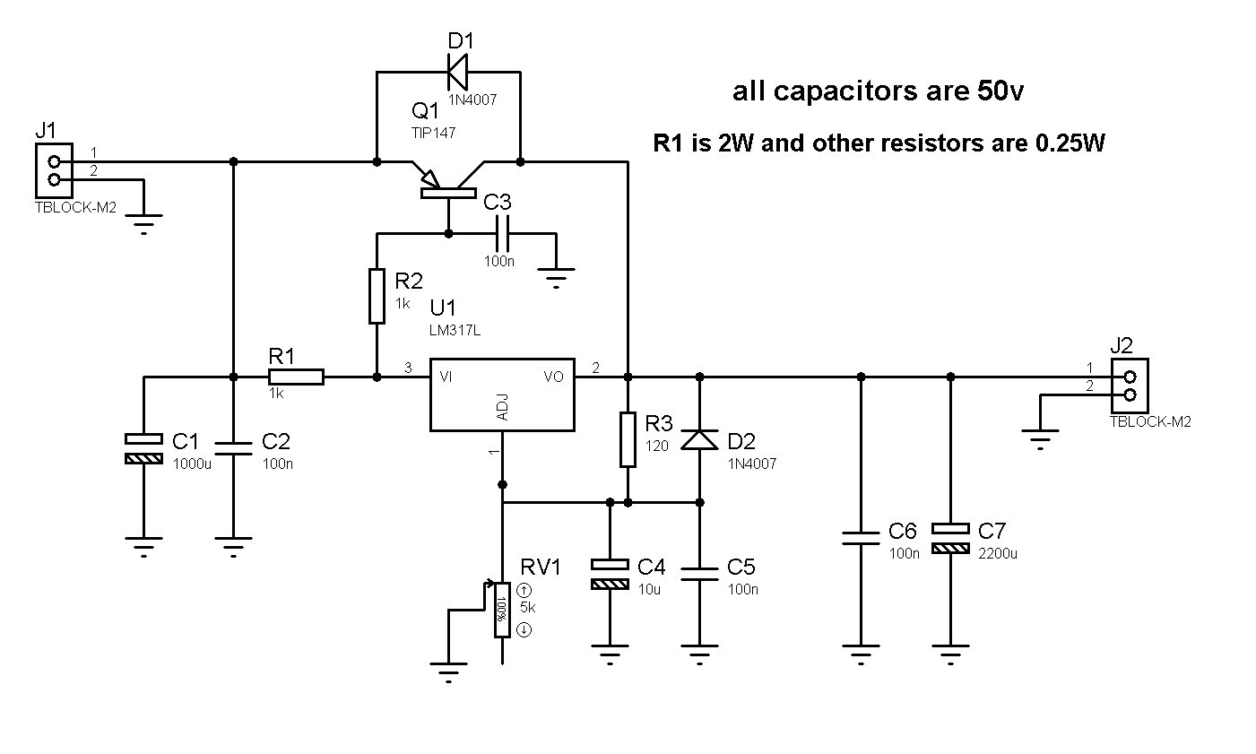 This is very simple 1.2 - 36V adjustable bench power supply with 5A of output current. Max input voltage is 37V and output is adjustable via potentiometer between 1.2 up to 36 volts. TIP147 PNP darlington transistor boosts the current of LM317 from 100mA to 5A. LM317 is the most useful and inexpensive adjustable regulator and for this circuit you can also use LM317L that can give 100mA, that's enough for transistor bias. D1 and D2 are protection diodes because when you turn the circuit off the output capacitors are discharging and can damage the transistor or regulator. 100nf capacitors are in parallel with electrolytic capacitors to remove high frequency noise because large value electrolytic have large ESR and ESL and can't remove high frequency noise.
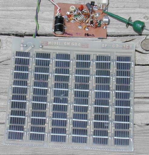
Posted on Wednesday, January 16, 2013 • Category: FM Transmitters
There are many miniature FM transmitter bug circuits online, this one is unique in that it runs completely on solar power. No battery is required. As long as the sun is shining on the PV panel, the transmitter will transmit. The transmitter bug is useful as a "remote ear", and can be used for anything from listening birds to surveillance work. The mic preamp and oscillator circuits were borrowed from a common circuit found around the Internet, a regulated solar power supply and an RF amp that extends the range of transmitter and improves frequency stability were added.
Circuit-Zone.com © 2007-2025. All Rights Reserved.
|
|
|