Circuit-Zone.com - Electronic Projects
Posted on Sunday, May 13, 2012 • Category: Power Supplies
This is a basic universal variable Power Supply voltage regulator circuit using an LM317, 3-terminal regulator in a TO-220package. The Universal Power Supply output voltage can be set to anywhere in the range 1.5V to 30V by selecting two resistances. By using a potentiometer, R2, as one of the resistors you can dial up the output voltage wanted. Either AC or DC input can be supplied to the PCB via a socket or terminal block. Connection can be either way around. This is because we have provided a bridge rectifier on board. The input DC voltage to the regulator must be at least 2.5V above the required output voltage. An off/on switch is provided.
For many applications (say 12V at 60mA) a heat sink will not be necessary. The LM317 will provide slightly higher output voltages than 30 volts. However, for most hobbyists over 30V will not be needed. So to make a small PCB we have used some electrolytic capacitors rated to 35 volts. To be safe for continuous operation the maximun input DC voltage to the regulator should not be over 33V. With a 2.5V to 3.0V drop across the regulator this will give a regulated output of 30V. You can draw up to 1.5A from the LM317. If you need higher then use an LM338T rated to 5A.
Posted on Tuesday, May 8, 2012 • Category: Amplifiers
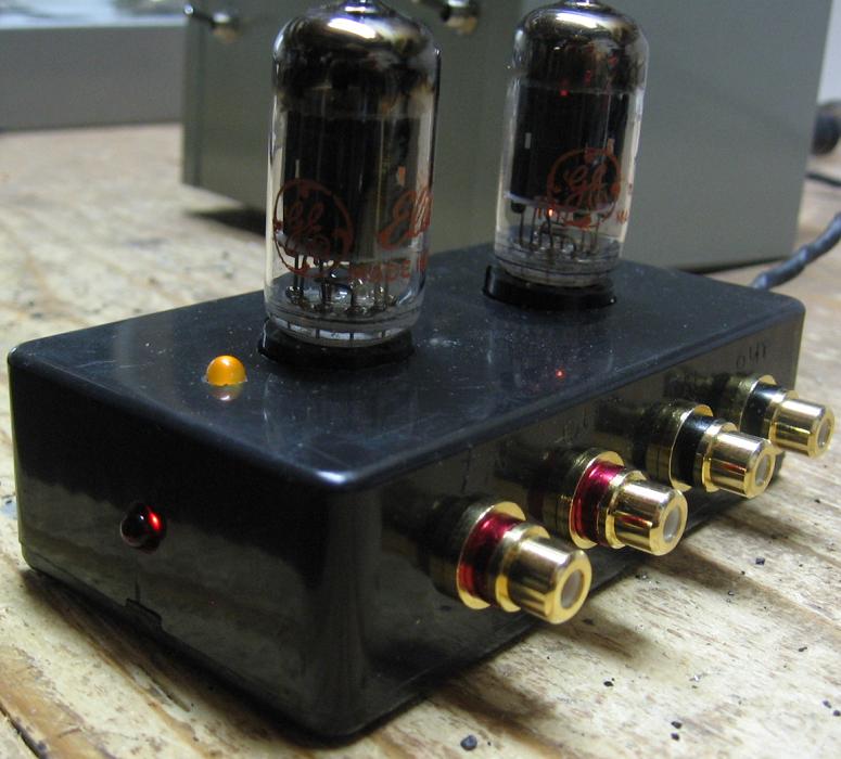 I'm not sure what motivated me to decide on building a high-gain tube preamp of this sort. Maybe it was the tube computer sound card idea I have seen, or the fact that I have enough junk to fill a dump truck. What ever it was, it all started with a cute little plastic Hammond enclosure that had been on my shelf for a couple of years. I originally thought I might use it for a tube headphone amp, but in the end realized there would not be enough space for the three tubes needed to make a head amp. This is a high gain preamplifier that is suitable for use where a lot of gain is required - to drive a power amplifier that needs plenty of gain or perhaps for use with instruments, like a guitar or microphone. If you need less gain, take a look at the RCA 12AU7 / ECC82 Cathode Follower Tube Preamp Schematic which has a gain of about 8.
Posted on Wednesday, May 2, 2012 • Category: FM Transmitters
 This is the schematic for an FM transmitter with 3 to 3.5 W output power that can be used between 90 and 110 MHz. Stability of this transmitter is not bad and PLL circuit can be added on.
This is a circuit that I've build a few years ago for a friend, who used it in combination with the BLY88 amplifier to obtain 20 W output power. From the notes that I made at the original schematic, it worked fine with a SWR of 1 : 1.05 (quite normal at my place with my antenna).
Posted on Friday, April 27, 2012 • Category: Headphone Amplifiers
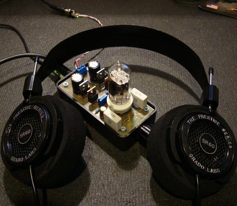 This is simple to build audiophile class-A tube headphone amplifier. It is based around 12AU7 / ECC82 audiophile vacuum tube that provides warm, rich and smooth sound expected from audiophile amplifiers. The 12AU7 (ECC82) is a Twin Triode vacuum tube, it is very popular in the audio world because it is rather rugged and can be operated at lower voltages. Headphone amplifier and 12AU7 tube is powered by just 12V DC voltage. This is great news for those new to vacuum tubes that want experience and learn more about them. Typically vacuum tubes operate at high and dangerous voltages so you must have some experience and know what you are doing. On the other hand this headphone amplifier operates at low 12V voltage so it is safe to build and experiment.
Posted on Monday, April 16, 2012 • Category: Headphone Amplifiers
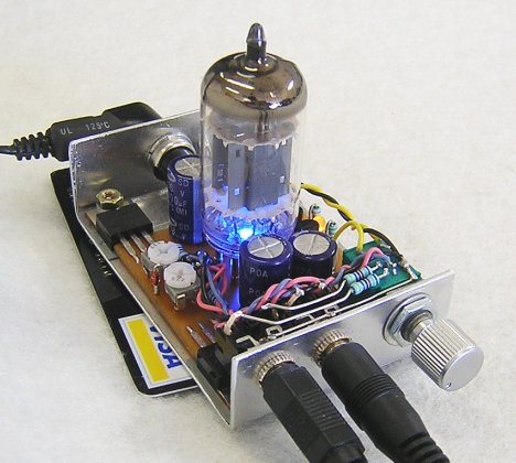 Simple Hybrid Headphone Amplifier DIY Audio Project. Rogers has put together a very simple hybrid headphone amplifier. The head amp uses a 12AU7/ECC82 vacuum tube for voltage gain stage and a IRF612 MOSFET follower biased in Class A with a passive CCS. What is nice about the project is that both the tube and MOSFET operate off of a 24V external switch mode power supply. Read on for more details about 12AU7 Tube / IRF610 MOSFET Hybrid Headphone Amplifier.
Posted on Sunday, April 15, 2012 • Category: Headphone Amplifiers
 Portable Headphone Amplifier powered by just 3 Volts.
Notes:
* Can be directly connected to CD players, tuners and tape recorders.
* Tested with several headphone models of different impedance: 32, 100, 245, 300, 600 & 2000 Ohm.
* Schematic shows left channel only.
* B1, SW1, J1 & C3 are common to both channels.
* R3 value was calculated for headphone impedance up to 300 Ohm. Using 600 Ohm loads or higher, change R3 value to 100K.
Posted on Tuesday, April 10, 2012 • Category: Amplifiers
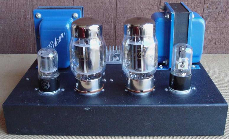 This Class-A Push-Pull Tube Power Amplifier uses a Pair of Push-Pull Class A, Ultra Linear Mono Block Tube Amplifiers that can be used with several different vacuum tubes including KT77 / 6L6GC / KT88 with a 12SL7 driver and 6NO30 tubes. The amplifier stage is based on the Compact Hi-Fi Power Amplifier. One thing about DIY audio is that it is a journey, not a destination, it never ends. One project leads to another. The only limits are time and money. DIY audio is a lot about perfection. While I was quite happy with my previous tube amplifier projects, I felt there was room to improve (here comes the journey again). I like to be involved in the music. If anything sticks out, it will degrade the experience. So I tend to like smooth response, lots of detail, wide soundstage and full spectrum of sound. These amps deliver all that in quantity. Regardless of what tubes I used for outputs, the sound is "silky" and refined.
Posted on Sunday, April 1, 2012 • Category: FM Transmitters
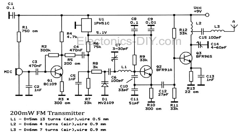 A simple 200mW FM Transmitter circuit which covers frequencies from 88 to 108 MHz. It is built with 3 transistors: BC109, BFR91A and BFR96S. It is quite stable and the output power is around 200mW.
The first stage of transmitter is a mic amplifier but if you connect this radio transmitter directly to an audio source you can remove this stage and connect the audio signal to R5.
U1, 1PH51C can be replaced with LM7805. You must use a stabilized power source for oscillator stage to prevent frequency variation. You can remove C7 and use a linear potentiometer instead of R6 with the median connector to C4, one pin to ground and the other one to +. FM Transmitter uses MV2109 varicap diode and C7 for frequency tuning.
Posted on Saturday, March 31, 2012 • Category: Amplifiers
 A general purpose audio power amplifier is a must have for the electronics amateur. It's not a good thing to use your HiFi set for an experiment, when there's a risk of blowing it's transistor out. Amplifier for your experiments should be simple in construction, durable, and easy to repair. Also a portable, low power consumption and battery powered.
Taking the considerations above, I gave you the PCB design for the TBA820M based amplifier. It is rated for 2Watts of RMS power output (16W PMPO) but gives even two times more if you cool it well by some tricks. I've been using this circuit for over ten years and personally still surprised by it's durability, thinking of how many short circuits and overdrives it is subjected.
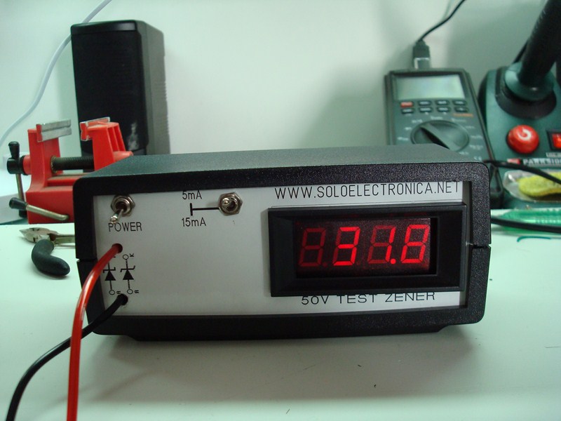
Posted on Friday, March 23, 2012 • Category: Test and Measurement
Presented here is zener diode meter for testing voltage value of an unknown zener diode. The zener diode or diode voltage regulator is a special diode, Unlike normal diodes these diodes are intended to work in the breakdown voltage and an essential part of the voltage regulator circuits.
These components maintain constant voltage at its terminals suffer variations even when substantial current, its connection with reverse bias is normal also to work in the zener voltage of the source Vs must be greater than the rupture Vz, as always condition using a resistance Rs in series to limit current to a value always less than its maximum power.
Circuit-Zone.com © 2007-2025. All Rights Reserved.
|
|
|