Circuit-Zone.com - Electronic Projects
Posted on Tuesday, May 17, 2011 • Category: FM Radio / Receivers
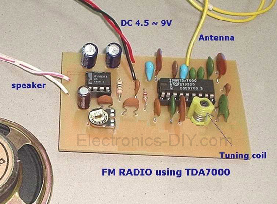
This project is a FM Radio based on TDA7000 and LM386 integrated circuits. What is unusual about TDA7000 IC is how it operates. It is a proper FM superhet receiver, with the usual local oscillator, mixer, IF amplifier, limiter, and phase detector. The difference is that there's only one tuned circuit; the local oscillator. Like the Pulse Counting Receiver, the TDA7000 relies on a low IF so that ordinary Op Amp circuitry can take care of the gain and bandpass characteristics. Only 70Kc/s is used with the TDA7000. Now, you might remember that the deviation of a broadcast FM signal is +/- 75Kc/s. A fully modulated signal would therefore sound rather distorted. So, how can this IC work?
It's quite simple in that there is what Philips call a Frequency Locked Loop. Basically, the local oscillator is shifted in response to detector output so that the bandwidth of the mixer output is never more than +/- 15Kc/s. It is actually compressing the frequency range of the modulated signal.
The muting or squelch feature is novel to say the least. Although it performs as any other muting circuit does, the TDA7000 provides an artificial noise generator so that the receiver still sounds alive while tuned off station. If you don't need that feature, just remove the .022uF condenser at pin 3. Not all Philips data sheets show it, but connecting a 10K resistor from the supply to pin 1 will disable the squelch.
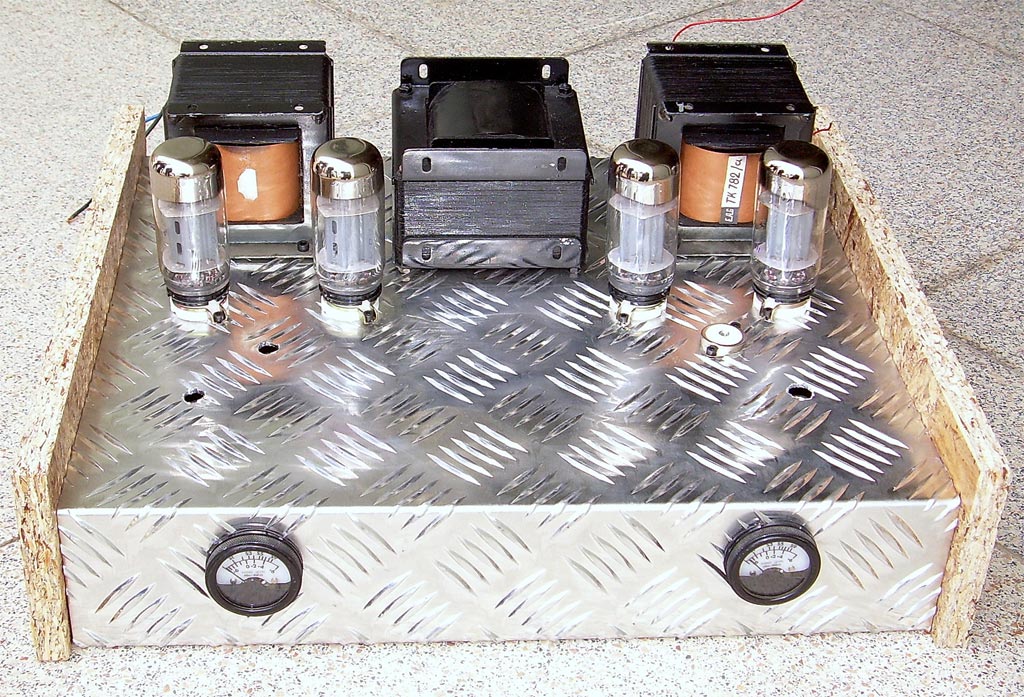
Posted on Monday, May 16, 2011 • Category: Amplifiers
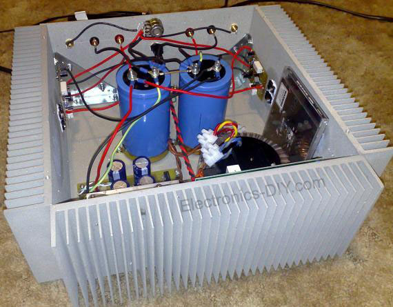 This is 8W Class A Amplifier I recently built. I am very pleased with the sonic results of this amplifier. It really does not disappoint. Even using fairly standard 3 way speakers in a large room, surprisingly there is ample power. What strikes me the most is the ability of this amplifier to differentiate between instruments and noises in the sound stage. This clarity is what I like most and I think this is achieved by deceptively simple and pure circuit topology.
I used the original board layout, transistors and JFETs, and made some modifications. Heat sinking was increased to approximately triple the amount recommended. Instead of using the standard bridge rectifier, capacitor bank and battery setup, I opted for a fully regulated supply with a total of 127,0000 uF capacitance per channel and a 500 VA toroid transformer.
Posted on Sunday, May 15, 2011 • Category: Battery Chargers
 Here is a simple battery charger circuit intended for 12 Volt gell-type battery. Current is limited by the 7805 regulator IC and the limiting resistor (62 ohms) to approximately 250 milliamperes, anyway most small sized gell-type battery capacities ranges from 2.5AH to 7.5AH so charging time should take several hours. When the battery is full, the regulator adjust its voltage output from 15 volts down to 5 volts automatically terminate the charging process.
Posted on Saturday, May 14, 2011 • Category: Battery Chargers
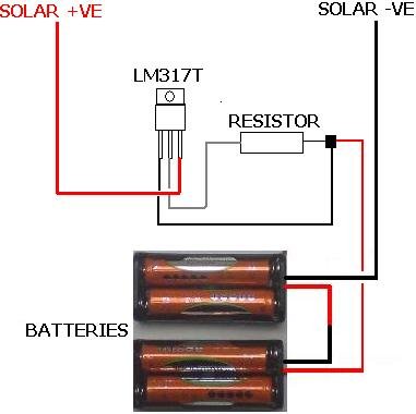 This is a solar panel battery charger schematic for AA and AAA rechargeable batteries. A small solar panel would be very good as a source of voltage charger. Building a solar AA battery charger only requires a few components and a simple construction.
Solar panels should be well adapted to the battery to be charged or the battery may be overcharged. If you want to charge batteries with different capacities, then you need to change the solar panels.
Since this is a simple solar battery charger that does not automatically turn off when the battery is full. So we need to maintain the charging current is low enough that will not damage the battery even when they are fully charged.
An LM317T voltage regulator chip that can be used with a suitable resistor to regulate current. See solar AA battery charger
Posted on Friday, May 13, 2011 • Category: Sensors
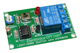 A simple light / dark activated relay switch circuit, suitable for many applications like the automatic switching of the lights in a shop window or a room according to the ambient light level. The circuit uses a light dependent resistor (LDR). A light/dark option has been incorporated. The term 'light/dark' is used because the circuit has a PCB-mounted switch on board. In one switch position a light-to-dark transition will activate the relay. In the other position a dark-to-light transition is required. So you can use the falling light on the detector to switch on a normally off circuit or switch off a normally on circuit. The relay is on when LDR uncovered and relay off when LDR covered. Adjust VR1 for light sensitivity. LED will turn on at the same time with relay.
Posted on Thursday, May 12, 2011 • Category: Phone Circuits
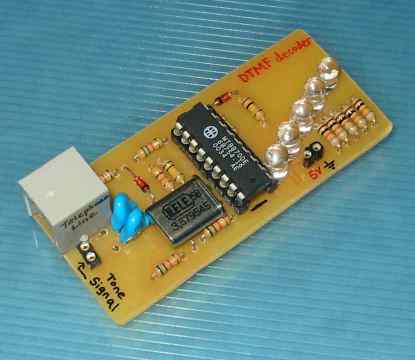 This circuit detects the dial tone from a telephone line and decodes the keypad pressed on the remote telephone. The dial tone we heard when we pick up the phone set is call Dual Tone Multi-Frequency, DTMF in short. The name was given because the tone that we heard over the phone is actually make up of two distinct frequency tone, hence the name dual tone. The DTMF tone is a form of one way communication between the dialer and the telephone exchange.
A complete communication consist of the tone generator and the tone decoder. In this article, we are use the IC MT8870DE, the main component to decode the input dial tone to 5 digital output. These digital bits can be interface to a computer or microcontroller for further application eg. remote control, phone line transfer operation, LEDs, etc...
Posted on Thursday, May 12, 2011 • Category: Power Supplies
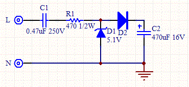 Simple, low cost and easy to build power supply. Ideal for applications that doesn’t require too much power. It can provide power to circuit that uses less than 100mA without any problem. The disadvantage of this circuit is the danger of an electrical shock, so it cannot be used if the circuit is in contact with the user. The voltage supplied by this is determined by the zener diode.
Posted on Wednesday, May 11, 2011 • Category: Amplifiers
 I wanted to make this HI-FI Valve Amplifier so that MCS can be considered a classic brand like a lot, but my hand veteran tuner anfimden kopamıyordum transistor amplifier at the end of this one day I decided to take it in my hand as long as I have somehow amplifier kurtulamayacaktım air after breakfast and drinking my tea I gave trying to check if the decision is correct Cry with her almost 15 years we have not shared this with less than animism, but cherish her love of rock music by pressing the send us compelled to take this tube amplifier device bitirebilecektim yes, I was sure before I took a friend who wants to
3 months without music ... without it stood late Tagged with kamçılandım ITSELF HERE:)
Posted on Tuesday, May 10, 2011 • Category: Arduino
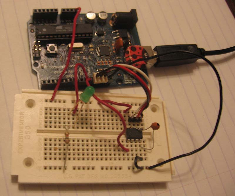 Randall converted an Arduino into AVR chip programming hardware for use with AVRDude. The project programs AVR tiny13 and other tiny AVR chips using an Arduino. He provides code and instructions to implement the Atmel AVR910 In System Programming protocol. I ported the Atmel AVR910 In System Programmer protocol to the Arduino. Now I can write programs to my ATtiny2313 and tiny13 chips. The Arduino sketch is available for download here. It works with the AVRDude programming software. This article will show how to use the Arduino to upload a program to the tiny13. The first step is to download the zip, extract the .pde file, then load it into the Arduino IDE, and write it to the Arduino. Next we can hook up the tiny13 chip.
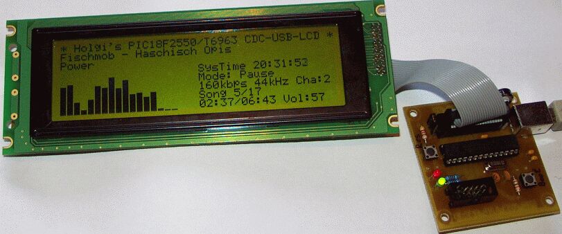
Posted on Tuesday, May 10, 2011 • Category: Test and Measurement
This is PIC18F2550 based Spectrum analyzer mod for PC. It uses WG24064A 240x64 graphical LCD with T6963 controller to display the result.
Circuit-Zone.com © 2007-2025. All Rights Reserved.
|
|
|